 DamaSight
Straight layers, random & twist
Connect the operation to the internal structure, then to the surface that reveals it.
Straight layers: plan the crossing.
After joining, drawing out, and any restacking, plan the angle between the layers and the final surface. Layers parallel to the broad face may show mostly on a bevel; changing their orientation can bring stripes onto a larger plane. Layer direction, thickness, and surface slope matter together.
For a given layer thickness, a surface closer to parallel can space the intersection lines farther apart. At exact parallelism it may stop crossing layers altogether. Actual curvature and uneven thickness further change the result.
Random patterns: disturb, then expose.
Uneven hammering, local relief, or removal followed by further deformation can move the layers to different heights. Grinding then crosses different materials at different positions. This is not random color applied to a surface, and uniform thinning does not necessarily create complex waves. Retain enough material to reach the intended disturbed region. [17] [68]
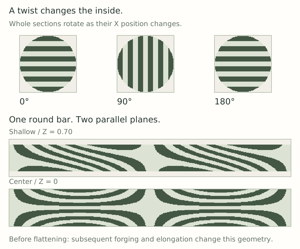
Twist: rotate the section along the length.
- Begin with a sound billet and an appropriate precursor section. Folded-in corners can become cold shuts rather than pattern features.
- Under a suitable, validated hot-working condition, rotate different X positions by different amounts. Uneven heat can concentrate rotation locally. [18]
- Compare section depth. A shallow plane crosses a narrower chord of a round bar; a central plane reveals a different width and layer arrangement.
- Account for subsequent flattening, joining, drawing out, and forming. Each continues to transform the earlier twist.
- Clean and compare corresponding regions and faces. One bar need not reveal identical motifs at every depth.
Twist density = complete turns / actual twisted length. Later drawing out changes this comparison. For a local twist, use the affected length rather than the whole bar. Density does not establish weld quality.
Multiple bars: combine existing structures.
Define handedness from the same viewing end, number the bars, and track their contact faces. Opposite twists can form mirrored combinations, but phase, width, arrangement, later elongation, and grinding depth influence how they meet. Adding bars is not simply multiplying a layer-count calculator. [56] [57] [76]
The Pattern Notebook · 8 of 18Visual learning. Real-world results vary.