 DamaSight
Ladder & raindrop
Separate removal from deformation. Then identify the plane that crosses the changed layers.
Ladder: two different causal sequences.
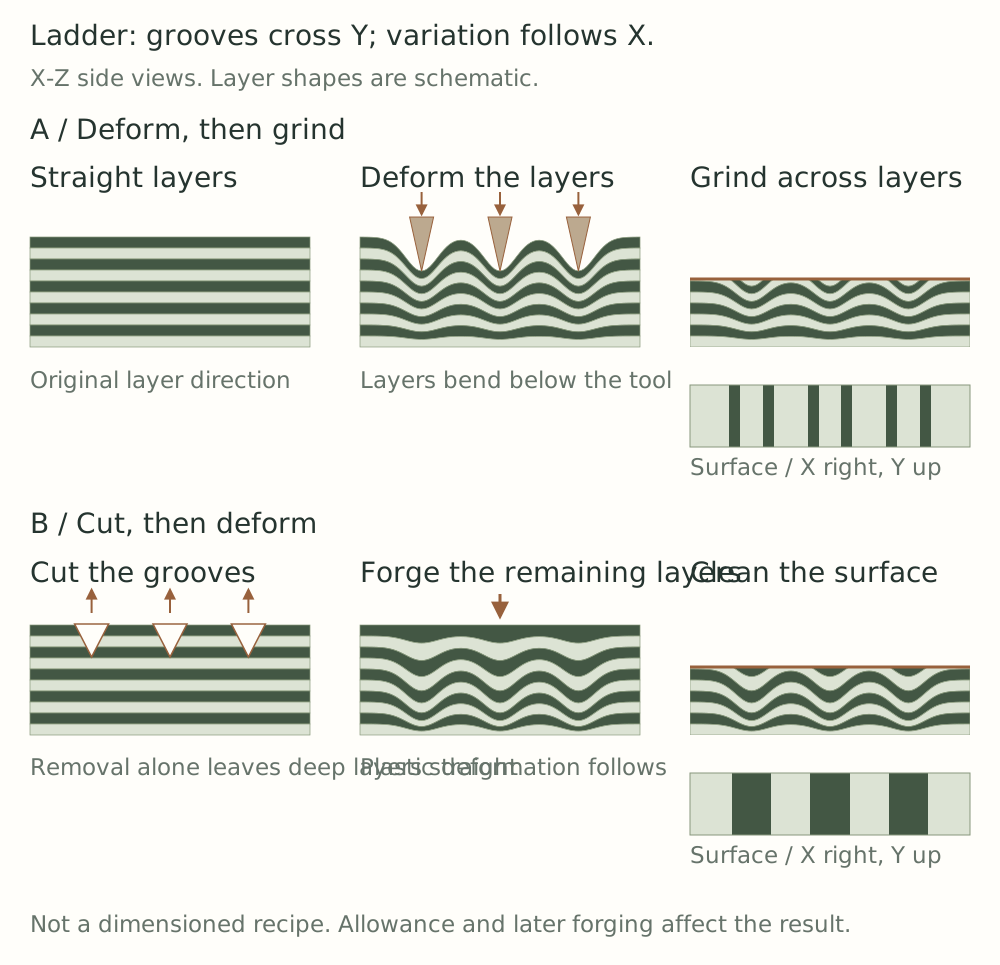
A transverse ladder groove typically runs across Y, with layer variation repeating along X. Ask which operation bends the layers, and which later surface intersects them.
Deform first, then grind.
- Prepare a sound layered billet with suitable allowance and recorded orientation.
- A transverse die changes both the exterior and the internal layer shape through local material movement.
- Grinding removes high material and exposes different layers around the depressed region.
- Beveling and any later forging alter the depth and spacing again. Verify the chosen route on a sample.
Nick Wheeler’s process and John White’s discussion distinguish this route from removal followed by deformation. They are related ideas, not interchangeable descriptions of one recipe. [64] [65]
Remove first, then deform.
- Cut or grind transverse grooves. The tool removes material; layers below the cut can still be straight.
- Prepare the newly exposed surfaces and forge the shape. The remaining layers bend, shift, and thin through deformation.
- Clean and grind a new display plane through that structure. Later elongation changes the repeat spacing.
Mick Maxen’s example uses staggered grooves on opposite sides before forging. Depth, spacing, offset, and final thickness are coupled variables, not universal dimensions. [66]
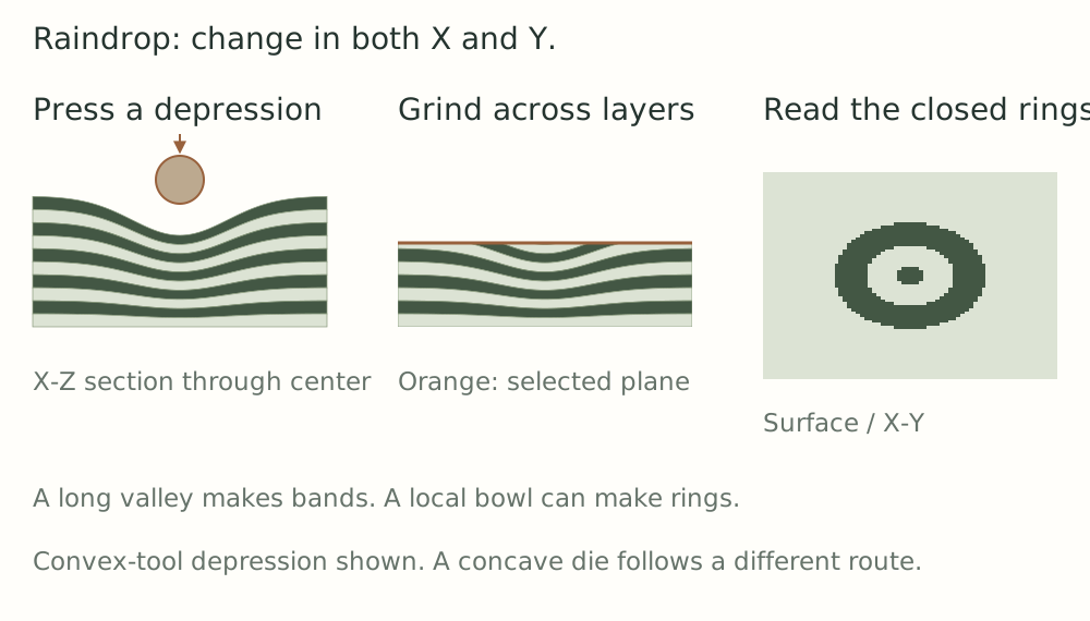
Raindrop: change a long valley into a local bowl.
A convex tool pressing a depression can bend layers in both X and Y. A flat surface through the bowl-shaped layers reveals closed material bands. A concave die can instead create a raised region that is later removed. These tool directions must be distinguished. Gene Martin’s example illustrates the concave-die route. [67]
Drilling or machining a pit first is another route. Drilling alone removes material; a subsequent deformation step is needed to bend remaining layers. The exposed rings depend on pit shape, layer thickness, flow, and section depth, so a hole does not guarantee concentric rings. [21]
Read the result along the process chain.
- Only shallow marks? Confirm that internal layers actually changed shape.
- Few broad bands? Compare layer thickness, deformation depth, and section position.
- Pattern fades with grinding? The surface may have passed beyond the disturbed region.
- Spacing varies along the workpiece? Look for later local drawing out.
- Cracks, folded edges, or open seams? Investigate structural defects before judging the pattern.
The Pattern Notebook · 9 of 18Visual learning. Real-world results vary.